 |
Ш§ЩҶШ¬Щ…ЩҶ ШұШ§ ШҜШұ ЪҜЩҲЪҜЩ„ Щ…ШӯШЁЩҲШЁ Ъ©ЩҶЩҠШҜ :
|
|||||||
| Ш«ШЁШӘ ЩҶШ§Щ… | Ш§ШұШіШ§Щ„ ШҜШ№ЩҲШӘЩҶШ§Щ…ЩҮ ШЁЩҮ ШҜЩҲШіШӘШ§ЩҶ ! | ШұШ§ЩҮЩҶЩ…Ш§ЩҠ ШіШ§ЩҠШӘ | Community | ШӘЩӮЩҲЩҠЩ… | Ш§ШұШіШ§Щ„ЩҮШ§ЩҠ Ш§Щ…ШұЩҲШІ | Ш¬ШіШӘШ¬ЩҲ |
 |
| ШӘШЁЩ„ЩҠШәШ§ШӘ ШіШ§ЩҠШӘ | |||||||||||||||||||||||||||||||||||||
  |
|
|
LinkBack | Ш§ШЁШІШ§ШұЩҮШ§ЩҠ ШӘШ§ЩҫЩҠЪ© | ЩҶШӯЩҲЩҮ ЩҶЩ…Ш§ЩҠШҙ |
|
|
#1 (Щ„ЫҢЩҶЪ© ШҜШ§ШҰЩ…) |
|
Administrator
 |
ШҙШЁЪ©ЩҮ ЫҢ ЩҮЩ…ЫҢЩҶЪҜ (Hamming Network)
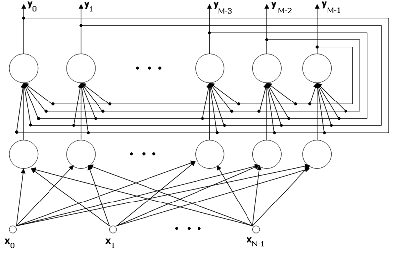
Щ…ЩӮШҜЩ…ЩҮ ЩӮШЁЩ„ Ш§ШІ ШҙШұЩҲШ№ ШЁШӯШ« ШұШ§Ш¬Ш№ ШЁЩҮ ШҙШЁЪ©ЩҮ ЫҢ ЩҮЩ…ЫҢЩҶЪҜ ШЁШ§ЫҢШҜ ШЁШ§ ШЁШұШ®ЫҢ Ш§ШөШ·Щ„Ш§ШӯШ§ШӘ ШўШҙЩҶШ§ ШҙЩҲЫҢЩ…. Ш§ЩҲЩ„ЫҢЩҶ ШӘШ№ШұЫҢЩҒ Щ…ШұШЁЩҲШ· ШЁЩҮ ЩҒШ§ШөЩ„ЩҮ ЫҢ ЩҮЩ…ЫҢЩҶЪҜ Щ…ЫҢ ШҙЩҲШҜ. ЩҒШ§ШөЩ„ЩҮ ЫҢ ЩҮЩ…ЫҢЩҶЪҜ ШЁЫҢЩҶ ШҜЩҲ ШЁШұШҜШ§Шұ X ЩҲ Sj ШЁШұШ§ШЁШұ ШӘШ№ШҜШ§ШҜ Щ…ЩҲЩ„ЩҒЩҮ ЩҮШ§ЫҢ ШҜЩҲ ШЁШұШҜШ§Шұ Ш§ШіШӘ Ъ©ЩҮ ШЁШ§ ЩҮЩ… Щ…ШӘЩҒШ§ЩҲШӘ ЩҮШіШӘЩҶШҜШҢ Ъ©ЩҮ ШЁШ§ dj ЩҶЩ…Ш§ЫҢШҙ ШҜШ§ШҜЩҮ Щ…ЫҢ ШҙЩҲШҜ. ШӘШ№ШұЫҢЩҒ ШЁШ№ШҜЫҢ Щ…ШұШЁЩҲШ· ШЁЩҮ Щ…ЩҒЩҮЩҲЩ… Щ…ЫҢШІШ§ЩҶ ШӘШҙШ§ШЁЩҮ ШҜЩҲ ШЁШұШҜШ§Шұ Ш§ШіШӘ. Щ…ЫҢШІШ§ЩҶ ШӘШҙШ§ШЁЩҮ ШҜЩҲ ШЁШұШҜШ§Шұ Ш№ШЁШ§ШұШӘШіШӘ Ш§ШІ ШӘШ№ШҜШ§ШҜ Щ…ЩҲЩ„ЩҒЩҮ ЩҮШ§ЫҢ ШЁШұШ§ШЁШұ ШҜЩҲ ШЁШұШҜШ§ШұЪ©ЩҮ ШўЩҶ ШұШ§ ШЁШ§ aj ЩҶЩ…Ш§ЫҢШҙ Щ…ЫҢ ШҜЩҮЩҶШҜ. ЩҫШі ШЁШ§ ШӘЩҲШ¬ЩҮ ШЁЩҮ ШӘШ№Ш§ШұЫҢЩҒ Ш§ШұШ§ШҰЩҮ ШҙШҜЩҮ ШҜШ§ШұЫҢЩ…: aj=n-dj Ш§Ъ©ЩҶЩҲЩҶ Ш§ЪҜШұ ЩҒШұШ¶ Ъ©ЩҶЫҢЩ… Ъ©ЩҮ ШҜЩҲ ШЁШұШҜШ§Шұ ШҜЩҲ ЩӮШ·ШЁЫҢ ШЁШ§ШҙЩҶШҜ(ЩҒЩӮШ· ШӯШ§ЩҲЫҢ Щ…ЩӮШ§ШҜЫҢШұ 1 ЩҲ 1- ) ШўЩҶЪҜШ§ЩҮ Щ…ЫҢ ШӘЩҲШ§ЩҶ ШұЩҲШ§ШЁШ· ШІЫҢШұ ШұШ§ Ш§ШұШ§ШҰЩҮ ЩҶЩ…ЩҲШҜ: Sj.X=aj-dj=aj+aj-n=2aj-n , aj=0.5*Sj.X+0.5*n=0.5*Ssijxi+0.5*n Щ…ШҜЩ„ ШіШ§Ш®ШӘШ§ШұЫҢ ЫҢЪ© ЩҲШ§ШӯШҜ Ш§ШІ ШҙШЁЪ©ЩҮ ЫҢ ЩҮЩ…ЫҢЩҶЪҜ  ШЁШ№ШҜ Ш§ШІ Ш§ШұШ§ШҰЩҮ ЫҢ ШӘЩҲШ¶ЫҢШӯШ§ШӘ Ш§ЩҲЩ„ЫҢЩҮ Ш§Ъ©ЩҶЩҲЩҶ ШЁЩҮ ШЁШӯШ« ЩҫЫҢШұШ§Щ…ЩҲЩҶ ЩҮШҜЩҒ Ш§ШұШ§ШҰЩҮ ЫҢ Ш§ЫҢЩҶ ШҙШЁЪ©ЩҮ Щ…ЫҢ ЩҫШұШҜШ§ШІЫҢЩ…. ШҜШұ ШҙШЁЪ©ЩҮ ЫҢ ЩҮЩ…ЫҢЩҶЪҜ ШӘШ№ШҜШ§ШҜЫҢ Ш§ШІ ЩҶЩҲШұЩҲЩҶ ЩҮШ§ ШҙШЁЫҢЩҮ ШҙЪ©Щ„ ЩҒЩҲЩӮШҢ ШӘШ№ШҜШ§ШҜЫҢ ШЁШұШҜШ§Шұ ЩҶЩ…ЩҲЩҶЩҮ ШұШ§ Ш§ШұШ§ШҰЩҮ Щ…ЫҢ ШҜЩҮЩҶШҜ ЩҲ ШҙШЁЪ©ЩҮ Щ…ЫҢШІШ§ЩҶ ШҙШЁШ§ЩҮШӘ X ЩҲШұЩҲШҜЫҢ ШЁЩҮ ЩҮШұ ЫҢЪ© ШұШ§ ШЁШҜШіШӘ Щ…ЫҢ ШҜЩҮШҜ. ШЁШІШұЪҜШӘШұЫҢЩҶ Ш®ШұЩҲШ¬ЫҢ ШҙШЁЫҢЩҮ ШӘШұЫҢЩҶ ШЁШұШҜШ§Шұ ЩҶЩ…ЩҲЩҶЩҮ ШЁЩҮ X ШұШ§ Щ…ШҙШ®Шө Щ…ЫҢ Ъ©ЩҶШҜ. Ш§ЫҢЩҶ ШЁШІШұЪҜШӘШұЫҢЩҶ Ш®ШұЩҲШ¬ЫҢ ШұШ§ Щ…ЫҢ ШӘЩҲШ§ЩҶ ШЁШ§ Ш§ШіШӘЩҒШ§ШҜЩҮ Ш§ШІ ЫҢЪ© Щ„Ш§ЫҢЩҮ ШҙШЁЪ©ЩҮ ЫҢ MaxNet Щ…ШҙШ®Шө Ъ©ШұШҜ. ШіШ§Ш®ШӘШ§Шұ ШҙШЁЪ©ЩҮ ЩҮЩ…Ш§ЩҶЪҜЩҲЩҶЩҮ Ъ©ЩҮ ШҜШұ ШЁШ®Шҙ ШЁШ§Щ„Ш§ Ш§ШҙШ§ШұЩҮ ШҙШҜ Ш§ЫҢЩҶ ШҙШЁЪ©ЩҮ Ш§ШІ ШҜЩҲ ШЁШ®Шҙ ШӘШҙЪ©ЫҢЩ„ ЫҢШ§ЩҒШӘЩҮ Ш§ШіШӘШҢ ШЁШ®Шҙ Ш§ЩҲЩ„ Ъ©ЩҮ ЩҮШұ ЩҲШ§ШӯШҜ ШўЩҶ Щ…Ш№ШұЩҒ ЫҢЪ© ШЁШұШҜШ§Шұ Щ…ЫҢ ШЁШ§ШҙШҜ Ъ©ЩҮ ЩӮШөШҜ Щ…ЩӮШ§ЫҢШіЩҮ ЫҢ ЩҲШұЩҲШҜЫҢ ШЁШ§ ШўЩҶ ШұШ§ ШҜШ§ШұЫҢЩ… ЩҲ ЩҲШІЩҶ Ш§ШӘШөШ§Щ„Ш§ШӘ ШўЩҶ ЩҶЫҢШІ ШЁШұ Ш§ШіШ§Ші ШӘШ№Ш§ШұЫҢЩҒ Ш§ШІ ЩӮШЁЩ„ Щ…ШҙШ®Шө ЩҲ ШӘЩҶШёЫҢЩ… Щ…ЫҢ ШҙЩҲШҜШҢ ШЁШ®Шҙ ШҜЩҲЩ… ШҙШЁЪ©ЩҮ ЫҢЪ© Щ„Ш§ЫҢЩҮ ЫҢ ШҙШЁЪ©ЩҮ Щ…Ш§Ъ©Ші ЩҶШӘ Ш§ШіШӘ Ъ©ЩҮ Ш¬ЩҮШӘ ШӘШ№ЫҢЫҢЩҶ ШЁШІШұЪҜШӘШұЫҢЩҶ Ш®ШұЩҲШ¬ЫҢ Ш§ШІ ШЁШ®Шҙ Ш§ЩҲЩ„ Ш§ШіШӘЩҒШ§ШҜЩҮ Щ…ЫҢ ШҙЩҲШҜ ЩҲ ШЁШҜЫҢЩҶ Ш·ШұЫҢЩӮ Ъ©Ш§Шұ ШӘШҙШ®ЫҢШө ШҙШЁЫҢЩҮ ШӘШұЫҢЩҶ ШЁШұШҜШ§Шұ ШЁЩҮ ШЁШұШҜШ§Шұ ЩҲШұЩҲШҜЫҢ Ш§ЩҶШ¬Ш§Щ… Щ…ЫҢ ЪҜЫҢШұШҜ. ШҙЪ©Щ„ Ш°ЫҢЩ„ ШіШ§Ш®ШӘШ§Шұ Ш§ЫҢЩҶ ШҙШЁЪ©ЩҮ ШұШ§ ЩҶЩ…Ш§ЫҢШҙ Щ…ЫҢ ШҜЩҮШҜ. Щ…ШҜЩ„ ШіШ§Ш®ШӘШ§ШұЫҢ ШҙШЁЪ©ЩҮ ЩҮЩ…ЫҢЩҶЪҜ  Ш§Щ„ЪҜЩҲШұЫҢШӘЩ… Ъ©Ш§Шұ ШҙШЁЪ©ЩҮ ЩҒШұШ¶ Ш§ЩҲЩ„ЫҢЩҮ Ш°ЫҢЩ„ ШұШ§ ШҜШұ ЩҶШёШұ Щ…ЫҢ ЪҜЫҢШұЫҢЩ… : n : ШӘШ№ШҜШ§ШҜ Ш№ЩҶШ§ШөШұ ШЁШұШҜШ§Шұ ЩҲШұЩҲШҜЫҢ m : ШӘШ№ШҜШ§ШҜ ШЁШұШҜШ§ШұЩҮШ§ЫҢ ЩҶЩ…ЩҲЩҶЩҮ Sj ШҢ j=1,...,m : ШЁШұШҜШ§Шұ ЩҮШ§ЫҢ ЩҶЩ…ЩҲЩҶЩҮ 0- ШӘШ№ЫҢЫҢЩҶ ЩҲШІЩҶ ЩҮШ§ЫҢ ШҙШЁЪ©ЩҮ ШЁШұ Ш§ШіШ§Ші ШұШ§ШЁШ·ЩҮ ЫҢ Ш°ЫҢЩ„ wi,j=0.5sij ,i=1,...,n j=1,...,m 1- ШЁШұШ§ЫҢ ЩҮШұ ШЁШұШҜШ§Шұ X ЩӮШҜЩ… ЩҮШ§ЫҢ 2 Ш§Щ„ЫҢ 4 ШұШ§ Ш§ЩҶШ¬Ш§Щ… Щ…ЫҢ ШҜЩҮЫҢЩ…. 2- Щ…ШӯШ§ШіШЁЩҮ Ш®ШұЩҲШ¬ЫҢ Ш®Ш·ЫҢ ЩҲШ§ШӯШҜЩҮШ§: ,j=1,...,m  3- ШӘШ№ЫҢЫҢЩҶ Щ…ЩӮШ§ШҜЫҢШұ Ш§ЩҲЩ„ЫҢЩҮ ШҙШЁЪ©ЩҮ Щ…Ш§Ъ©Ші ЩҶШӘ yj(0)=yi j=1,...,m 4- Ш§Щ„ЪҜЩҲШұЫҢШӘЩ… Щ…Ш§Ъ©Ші ЩҶШӘ Ш§ЩҶШ¬Ш§Щ… Щ…ЫҢ ШҙЩҲШҜ |
|
|

|
| #ADS | |
|
ЩҶШҙШ§ЩҶ ШҜЩҮЩҶШҜЩҮ ШӘШЁЩ„ЫҢШәШ§ШӘ
ШӘШЁЩ„ЩҠШәЪҜШұ
ШӘШ§ШұЩҠШ® Ш№Ш¶ЩҲЩҠШӘ: -
Щ…ШӯЩ„ ШіЩғЩҲЩҶШӘ: -
ШіЩҶ: 2010
ЩҫШіШӘ ЩҮШ§: -
|
|
|
|
|
|
#2 (Щ„ЫҢЩҶЪ© ШҜШ§ШҰЩ…) |
|
Administrator
 |
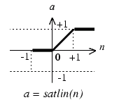
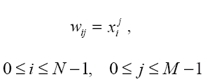
Subject: Applications of Artificial Intelligence Project: Hamming Neural Network - classifier Authors: StanisЕӮaw KamiЕ„ski, Marcin Samborski Translation: ЕҒukasz Adamowicz, Piotr Szopa Supervisor: MSc. Adam GoЕӮda HammingвҖҷs classifier вҖ“ description This project describes the properties, applications, and creation process of the Hamming Neural Network, working as the signals classifier. You may notice that the model of network described in this project may be a little different than one described in a professional literature. ThatвҖҷs because we created our network to implement it in the Matlab environment. Nevertheless, the network works correctly. What kind of signals does the Hamming Network process? Although the network works in an analog way, it processes binary signals вҖ“ on the other hand, those signals can be вҖңnoisyвҖқ, and have continuous values, not only zeros and ones. What does the Hamming Network look like?  In the picture presented above we can see the Hamming Network. It can be divided into two basic sections: * input layer вҖ“ a layer built with neurons, all of those neurons are connected to all of the network inputs; * output layer вҖ“ which is called MaxNet layer; the output of each neuron of this layer is connected to input of each neuron of this layer, besides every neuron of this layer is connected to exactly one neuron of the input layer (as in the picture above). ItвҖҷs easy to see, that both layers have the same number of neurons. How does the Hamming Network work? Input layer neurons are programmed to identify a fixed number of patterns; the number of neurons in this layer matches the number of those patterns (M neurons вҖ“ M patterns). Outputs of these neurons realise the function, which вҖңmeasuresвҖқ the similarity of an input signal to a given pattern. The output layer is responsible for choosing the pattern, which is the most similar to testing signal. In this layer, the neuron with the strongest response stops the other neurons responses (it usually happens after few calculating cycles, and there must be a вҖң0вҖқ on x(i) inputs during these cycles). There should be the вҖң1 of MвҖқ code used on the output, which points at the network answer (1 of M patterns is recognized). To achieve this, proper transfer function has to be used вҖ“ in our case the best function was  How are the connections weights created? Weights of the input layer neurons Those weights are set to assure that the maximal responses of all neurons are equal, and that exactly one pattern causes specific neuron to response. There is no need to teach network to achieve that, itвҖҷs sufficient to mathematically set weights. Weights of the input layer  where: * w(i,j) is the weight of the connection between neuron вҖңjвҖқ and the input вҖңiвҖқ * x(i,j) is the value of signal вҖңiвҖқ in pattern вҖңjвҖқ This equation becomes obvious, when we recall that the product of weights and impulses of a neuron can be interpreted as the cosinus of the angle between the weight vector and the impulse vector. When these vectors are equal, the neuron output will be вҖң1вҖқ, when vectors are different, the output value range will be from вҖ“1 to 1. Input weights of the output layer neurons At first, we need to determine the number of the output layer neurons inputs. Each of those neurons is connected: * to itself вҖ“ weight=1 * to all of neurons of the output layer вҖ“ weight of each connection is -1/M * to appropriate neuron of the input layer вҖ“ weight=1 An example To familiarize ourselves with the Hamming classifier, we made a network in the Matlab environment. Its task is to recognize 1 of 8 signs recorded in the network вҖңmemoryвҖқ. The picture below shows 8 used signs: Signs used as patterns  The matrices that represent these signs are two-dimensional (3x5 pixels), but it was more convenient to write them as a single row (15 positions) vectors. Black squares are ones, white squares are zeros. To make proper calculations, we normalised all of the row vectors. We want to classify 8 signs, so our network will contain 16 neurons, divided into 2 groups, 8 neurons in each layer. Weights of the input layer are predefined as transposed matrix of signs вҖ“ previously normalised. Weights of the output layer are defined according to the previously stated assumptions (see вҖҳInput weights of the output layer neuronsвҖҷ section), and the вҖҳвҖ“1/MвҖҷ parameter in our case was set to вҖҳвҖ“1/8вҖҷ. We cannot forget that it is necessary to normalise rows of that matrix. Neuron activation function that we have chosen is: Function  We assumed that 15 calculating cycles in the output layer will be sufficient to stabilize the network response; but we noticed that it can be not enough, when we are dealing with strong noise. It would be the best solution to check if there is a вҖң1вҖқ on exactly one of the outputs each cycle, but it would be difficult to predict the amount of time needed to perform the classification then вҖ“ and that is very important when working with DSP. The last part of the experiment was to add some noise to our signs and then examine the network. The вҖңanalogвҖқ noise is generated with rand() function. Summary The network we created works correctly вҖ“ it recognises given sign, even with noise, if only it is possible. It does not recognise properly when it is totally impossible to do it or when 2 neurons have strong responses, similar to each other вҖ“ it would take more calculating cycles to recognise it, then. References * prof. Ryszard Tadusiewicz, "Sieci neuronowe", Akademicka Oficyna Wydawnicza RM 1993 * prof. Andrzej Kos, "PrzemysЕӮowe zastosowania sztucznej inteligencji", Lecture Click here to download complete m-file: |
|
|

|
| Ш§ШІ Astaraki ШӘШҙЩғШұ ЩғШұШҜЩҮ Ш§ШіШӘ: | Faa916 (Ы°Ы№-ЫІЫ¶-ЫұЫіЫ№Ы¶) |
 |
«
Щ…ЩӮШҜЩ…ЩҮ Ш§ЫҢ ШЁШұ ШҙШЁЪ©ЩҮ ЩҮШ§ЫҢ Ш№ШөШЁЫҢ(Hagan)
|
ЩҒШ§ЩғШӘЩҲШұЩҮШ§ЩҠ ЩҲЩҠЪҳЩҮвҖҢ Щ…ШҜЩ„ ШӘШ·ШЁЩҠЩӮЩҠ ШҙШЁЩғЩҮ Ш№ШөШЁЩҠ ЩҒШ§ШІЩҠ ШҜШұ ЩҫЩҠШҙвҖҢШЁЩҠЩҶЩҠ ШӘШұШ§ЩҒЩҠЪ©
»
| ЩғШ§ШұШЁШұШ§ЩҶ ШҜШұ ШӯШ§Щ„ ШҜЩҠШҜЩҶ ШӘШ§ЩҫЩҠЪ©: 1 (0 Ш№Ш¶ЩҲ ЩҲ 1 Щ…ЩҮЩ…Ш§ЩҶ) | |
|
|
ШІЩ…Ш§ЩҶ Щ…ШӯЩ„ЩҠ ШҙЩ…Ш§ ШЁШ§ ШӘЩҶШёЩҠЩ… GMT +3.5 ЩҮЩ… Ш§Ъ©ЩҶЩҲЩҶ Ы°Ыҙ:ЫұЫі ЩӮШЁЩ„ Ш§ШІ ШёЩҮШұ Щ…ЩҠШЁШ§ШҙШҜ.


 Linear Mode


